Uploads by R-UK-29
Jump to navigation
Jump to search
This special page shows all uploaded files.
| Date | Name | Thumbnail | Size | Description | Versions |
|---|---|---|---|---|---|
| 22:06, 21 October 2014 | QNET SPL P3.jpg (file) |  |
62 KB | Sound Pressure Level of pressure fluctuations for P3 sensor. | 1 |
| 22:05, 21 October 2014 | QNET SPL P2.jpg (file) |  |
58 KB | Sound Pressure Level of pressure fluctuations for P2 sensor. | 1 |
| 22:05, 21 October 2014 | QNET SPL G3.jpg (file) |  |
60 KB | Sound Pressure Level of pressure fluctuations for G3 sensor. | 1 |
| 22:02, 21 October 2014 | QNET SPL G6.jpg (file) |  |
64 KB | Sound Pressure Level of pressure fluctuations for G6 sensor. | 1 |
| 22:01, 21 October 2014 | QNET SPL G9.jpg (file) |  |
56 KB | Sound Pressure Level of pressure fluctuations for G9 sensor. | 1 |
| 22:01, 21 October 2014 | QNET SPL P1.jpg (file) |  |
60 KB | Sound Pressure Level of pressure fluctuations for P1 sensor. | 1 |
| 21:32, 21 October 2014 | S8Ch WT ONERA ptabs.jpg (file) |  |
164 KB | Locations of the pressure tabs and Kulite sensors along the lower wall of the wind | 1 |
| 18:18, 21 October 2014 | S8Ch WT CFD VG mesh.jpg (file) |  |
153 KB | Surface view of the vortex generators on the bump. | 1 |
| 18:17, 21 October 2014 | S8Ch WT CFD VG topology.jpg (file) |  |
69 KB | Multi-block topology around the CoC1-VGs device. | 1 |
| 18:16, 21 October 2014 | S8Ch WT CFD topology.jpg (file) |  |
103 KB | Overview of the multi-block topology for the S8Ch wind tunnel. | 1 |
| 18:15, 21 October 2014 | S8Ch WT CFD domain.jpg (file) |  |
64 KB | Full domain of the S8Ch wind tunnel. | 1 |
| 17:29, 21 October 2014 | Example.jpg (file) |  |
64 KB | Full domain of the S8Ch wind tunnel. | 5 |
| 16:47, 20 August 2014 | QNET oilflow URANS.jpg (file) |  |
736 KB | Oil flow visualisation for steady shock wave configuration w/o control (a) and with co-rotating VGs (b) for URAN calculations. The red line indicates the end of the bump. | 1 |
| 16:42, 20 August 2014 | QNET oilflow exp.jpg (file) |  |
948 KB | Oil flow visualisation for steady shock wave configuration w/o control (a) and with the co-rotating VGs (b). Red line indicates the end of bump. | 1 |
| 17:39, 9 July 2014 | S8Ch WT CFD VGs.jpg (file) |  |
271 KB | 1 | |
| 10:29, 9 July 2014 | ONERA VG CoC1 12p5mm1.jpg (file) |  |
24 KB | Schlieren visualizations for the steady shock wave configuration with control devices. | 4 |
| 09:57, 9 July 2014 | URANS separation.jpg (file) |  |
61 KB | Comparison between experimental and URANS computational histories of the size of the separated flow region for the 30Hz forced shock oscillation configuration without any control devices. | 1 |
| 09:51, 9 July 2014 | URANS shockposition.jpg (file) |  |
66 KB | Comparison between experimental and URANS computational histories of shock position for 30Hz forced shock oscillation without any control device. | 2 |
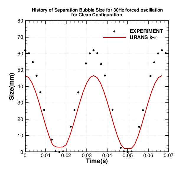
| 14:17, 25 June 2014 | QNET clean separation.jpg (file) |  |
61 KB | Time history of separation bubble size in median plane for the clean case in 30Hz forced oscillation. | 1 |
| 14:16, 25 June 2014 | QNET clean shockposition.jpg (file) |  |
66 KB | Shock position in median plane for the clean case in 30Hz forced oscillation. | 1 |
| 14:15, 25 June 2014 | QNET oilflow URANS control.jpg (file) |  |
61 KB | Oil flow visualisation for steady shock wave configuration with CoC1 VGs during URANS computations. | 1 |
| 14:14, 25 June 2014 | QNET oilflow URANS clean.jpg (file) |  |
36 KB | Oil flow visualisation for steady shock wave configuration without control during URANS computations. | 1 |
| 14:11, 25 June 2014 | QNET oilflow exp control.jpg (file) |  |
144 KB | Oil flow visualisation for steady shock wave configuration with CoC1 VGs during experiments. | 1 |
| 14:10, 25 June 2014 | QNET oilflow exp clean.jpg (file) |  |
136 KB | Oil flow visualisation for steady shock wave configuration without control during experimental. | 1 |
| 14:07, 25 June 2014 | QNET control isentropic mach.jpg (file) |  |
60 KB | Isentropic Mach number distribution along the lower wall for diagonal shaft location for Quasi-steady shock configurations with and without vortex generators. | 1 |
| 14:06, 25 June 2014 | QNET control pressureratio.jpg (file) |  |
64 KB | Static pressure distribution along the lower wall for diagonal shaft angle for quasi-steady shock configuration with and without vortex generators. | 1 |
| 14:00, 25 June 2014 | QNET clean cf vertical.jpg (file) |  |
59 KB | Skin friction coefficient on upper and lower wall for vertical shaft angle. | 1 |
| 13:59, 25 June 2014 | QNET clean cf diagonal.jpg (file) |  |
62 KB | Skin friction coefficient on the upper and lower wall for diagonal shaft angle. | 1 |
| 13:58, 25 June 2014 | QNET clean cf horizontal.jpg (file) |  |
60 KB | Skin friction on upper and lower wall for horizontal shaft angle. | 1 |
| 13:53, 25 June 2014 | QNET clean pressure vertical.jpg (file) |  |
68 KB | Static pressure distribution in median plane for vertical shaft angle. | 1 |
| 13:50, 25 June 2014 | QNET clean pressure diagonal.jpg (file) |  |
69 KB | Static pressure distribution in median plane for diagonal shaft angle. | 1 |
| 13:48, 25 June 2014 | QNET clean pressure horizontal.jpg (file) |  |
72 KB | 1 | |
| 22:37, 24 June 2014 | ONERA exp up.jpg (file) |  |
27 KB | 1 | |
| 22:34, 24 June 2014 | ONERA control up.jpg (file) |  |
18 KB | 1 | |
| 22:32, 24 June 2014 | ONERA Reference 12p5mm.jpg (file) |  |
76 KB | 1 | |
| 14:24, 24 June 2014 | CoC1 VG schematic.jpg (file) |  |
16 KB | 1 | |
| 14:19, 24 June 2014 | S8Ch WT ONERA.jpg (file) |  |
122 KB | Sketch of the S8Ch wind tunnel in ONERA | 1 |
| 13:43, 24 June 2014 | Filename.extension (file) |  |
122 KB | 1 |