Abstr:Premixed Methane-Air Swirl Burner (TECFLAM)
Application Area 2: Combustion
Application Challenge AC2-08
Abstract
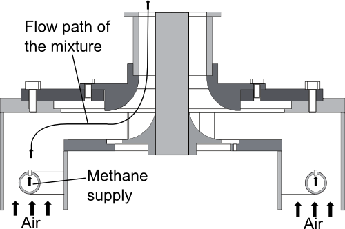
The TECFLAM configuration is a lean premixed methane-air burner with a high swirl intensity where the flame is stabilized by the recirculation of hot products. The test case presented here is a further development of the configurations defined within the TECFLAM (TEChnical FLAMes) project founded in 1984. Back then a co-operation between several German research institutions aimed to define burners to improve the understanding of combustion processes and to obtain validation data for simulations (see also AC2-06). The burner has been designed to investigate essential features found in industrial lean premixed combustors. An extensive set of measurements obtained by advanced laser-diagnostics exists to:
- Give insight into the underlying physics to gain a deeper understanding of the relevant phenomena
- Build a database well suited for CFD validation
Validation data is available for the reacting and non-reacting cases using the same velocity boundary conditions to allow for a separate assessment of the applied turbulence model and combustion model. A total of four cases are considered in this AC consisting of a 30 kW and 150 kW flame and their corresponding isothermal cases. The database for validation contains measurements of velocities, species mass fractions, temperature as well as integral length scales and the frequency spectrum at the nozzle exit. Simulation results obtained from RANS (Reynolds Averaged Navier Stokes) and LES (Large Eddy Simulation) investigations will be presented and compared with the experimental results.
Contributors: Guido Kuenne (EKT), Andreas Dreizler (RSM), Johannes Janicka (EKT)
EKT: Institute of Energy and Power Plant Technology, Darmstadt University of Technology
RSM: Institute Reactive Flows and Diagnostics, Center of Smart Interfaces, Darmstadt University of Technology
© copyright ERCOFTAC 2011


