Abstr:Draft tube
Application Area 6: Turbomachinery Internal Flows
Application Challenge AC6-07
Abstract
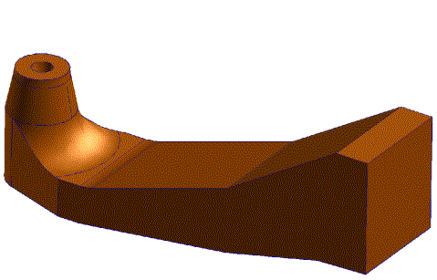
An experimental study has been performed of the flow in a sharp-heel draft tube for a Kaplan turbine. The measurements were made at the Turbine Testing Facility at Vattenfall Utveckling AB in Älvkarleby, Sweden. The draft tube is the curved diffuser downstream of the runner in a water turbine, and the purpose of the draft tube is to recover as much as possible of the kinetic energy of the flow after the runner. The efficiency loss in the draft tube is particularly important for low-head, high flow Kaplan power stations. The complete model consists of a 1:11 scale copy of the power station Hölleforsen including the rotating Kaplan runner, which has a diameter of 0.5 m. Figure 1.1 shows the draft tube. The Reynolds number ReD, based on runner diameter and average velocity is 1 750 000.
The flow in fluid machinery often involves the application of diffusers to convert kinetic energy in the fluid into pressure rise. A detailed understanding of the physics of the flow in such diffusers is of fundamental importance in order to improve the efficiency of the diffuser. The pressure recovery in a draft tube, which is the curved diffuser downstream of the runner in a water turbine, takes place in a very complicated geometry, which is determined by economic considerations regarding construction as well as fluid-mechanical considerations. Building costs are balanced against diffuser performance, and earlier designs (when building costs were relatively high) are optimised differently than modern designs. Whether the flow in the draft tube separates or not determines the ultimate pressure rise that can be achieved.
When refurbishing old hydro-power plants, there is therefore a potential for improving the pressure recovery in the draft tube by modifying the geometry of the draft tube. In order to utilise this potential, validated CFD tools are necessary.
The flow downstream of the runner in a water turbine, which is the inlet flow to the draft tube, is complicated with both a swirling mean flow, a periodic velocity component, and turbulence. The flow in the draft tube itself is composed by several co-existing flow phenomena or flow regimes: boundary layers in positive pressure gradient, flow curvature, flow rotation, and possibly (2- or 3-D) flow separation, thus creating a real application challenge. The test case put forward here is designed to test the ability of CFD codes to predict the pressure rise and flow field for such problems.
Contributors: Rolf Karlsson - Vattenfall Utveckling AB
{{#set:hasContributorOrg=Vattenfall Utveckling AB}} {{#set:hasContributorPerson=Rolf Karlsson}} {{#set:hasReviewerOrg=AEA Technology}} {{#set:hasReviewerPerson=Florian Menter}} {{#set:hasQualityAccessLevel=Gold}}

