UFR 3-04 Test Case
Laminar-turbulent boundary layer transition
Underlying Flow Regime 3-04 © copyright ERCOFTAC 2004
Test Case
Brief description of the study test case
The experimental facility consists of an open-circuit wind tunnel equipped with the disturbance (wake) generator and linear blade cascade. As a periodic generator a wheel with cylindrical bars rotating in a plane perpendicular to the flow direction is used. The wheel of pitch diameter Dp = 1950 mm has been driven by electric motor with adjustable rotating speed. The maximum tangential velocity measured on the pitch diameter of the wheel could be as high as umax@ 18m/s. The diameter of the bars could be changed and in the reported measurements the rods of d=4mm and 12mm mounted with a pitch 204 mm and 76.6 mm respectively were applied. The distance between generator and blade cascade is fixed and equal 34% of axial blade chord which is often encountered in real turbine stage.
The test section of linear blade cascade consisted of five blades and the measurements were performed on the middle one. The profile N3-60 applied in the research is an industrial one and it was used as a stator vane of high-pressure part of TK-200 turbine produced by Polish manufacturer (formerly ZAMECH now ABB ALSTOM). The tested profile is scaled 3.4 times to the original one. The main geometrical parameters of the cascade were: the blade chord length bs=300 mm, the pitch ts=240 mm, and the blade staggered angle as=43°35' . These values according to the results of research program performed previously at the Institute of Thermal Machinery TU of Czêstochowa were found to give the lowest profile losses. In the present configuration the rotor-stator axial gap has been set to 70 mm, what corresponds to the 34% of stator axial chord which is often encountered in real turbine stage. The location of moving cylindrical bars and stator profiles as well as the position of measuring planes has been shown on Fig. 1 and 2 which may be found at http://tajfun.imc.pcz.czest.pl/transpret and the most important flow and geometrical parameters are gathered in the Table 1. The Data Base was created under the TRANSPRETURB Thematic Network on Transition Project (EC Contract ERBICT 20-CT98-0005).
Table 1
 Application of a movable grid located upstream the cascade entrance enabled control of the freestream turbulence intensity Tu in a range from 0.5 to 9%. For present experiment its level was set to Tu=4%. The outlet velocity from the cascade was kept constant at c2=30 m/s that for the tested blades corresponded to a Reynolds number equal Re= c2 × bs/ν= 6*105. The inlet velocity on the cascade was equal 9.7 m/s, however the drop of the velocity between wind tunnel exit and the blade cascade from 14.5 m/s to 9.7 m/s was observed. This drop was due to unavoidable leakage of the medium through technical gaps in the plane of rotating wheel. Other detailed information concerning geometrical and flow parameters are given at http://tajfun.imc.pcz.czest.pl/transpret.
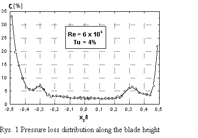
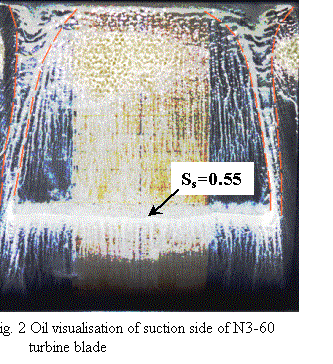
 The analysis of pressure loss distribution along the blade height shown in Fig. 1 reveals that a substantial portion of flow is free from secondary losses. Measurements were performed in the middle of the blade height that allows to treat the problem analysed as a two-dimensional one. To confirm this conclusion the oil surface visualization on the suction side of the blade was performed (see Fig. 2). The evolution of the secondary flows, bounded by the red dashed lines, is well seen, so one can conclude that the flow in the middle of the blade is not disturbed by their influence. The oil visualization shows also the small separation line, which is located just after minimum pressure point (for surface coordinate Ss=0.55). This last observation is important in the connection with the analysis of the boundary layer development discussed in chapter 6. It is worth to mention, that since single-wire probe was applied no correction on momentum and energy balance was possible.
Test Case Experiments
Experimental investigations of velocity field in the boundary layer have been performed using a single wire probe combined with the DISA 55M System hot-wire anemometer coupled to PC computer. The computer was equipped with 12-bit analog-digital (A/D) converter with the input range 0-12V. The hot-wire was calibrated in-situ before and after the experiment. Detailed measurements of boundary layer characteristics were performed in 54 cross-sections distributed along the suction and pressure sides of tested profile. At each station, the boundary layer was penetrated in 30-40 locations where a 40 sec signal was sampled with 25 kHz frequency.
Additionally, wall shear stresses have been measured with the use of surface mounted hot-film techniques. Because the in-situ calibration of surfaces gauges was not possible, it was decided to apply the semi-quantitative approach (Hodson, 1983), where the wall shear stresses have been calculated according to the formula
In this equation it was assumed that the rate of heat loss to the substrate, could be approximated using the square of voltage E0 for non-flow conditions and that the temperature difference was proportional to E02. For the present investigation the magnitude of E0 was controlled before and after data acquisition. The units associated with the quantity ωw are arbitrary, but this procedure allows the relative signals from individual gauges to be compared. During the experiment DANTEC hot-film gauge of 55R47 type has been used.
The uncertainty analysis of recorded signal revealed a measuring error of 10% for hot-wire signals and 15% for hot-films signals.
CFD Methods
The numerical analysis has been performed with the use of the unsteady UNNEWT+PUIM solver (Vilmin at al, 2002). The code UNNEWT is an unsteady version of the unstructured-mesh viscous flow solver NEWT (Dawes, 1992). The governing equations are discretised in space using the vertex based scheme with overlapping control-volumes, with fluxes being computed through the faces of triangular cells. Time integration of the discretised equations is carried out using second order four-step explicit Runge-Kutta time-stepping scheme. The blending of second order and fourth order artificial dissipation is used to damp numerical oscillations. The turbulence model used is the low-Reynolds number Yang and Shih k-ε model (Yang and Shih, 1993), with damping functions in the near-wall regions. In this model k1/2 is chosen as the turbulent velocity scale. The time scale Tt is bounded from below by the Kolmogorov time scale ![]() . That is why when this time scale is used to reformulate the dissipation equation, there is no singularity at the wall and so the introduction of a pseudo-dissipation rate is avoided. The model constants are exactly the same as those in the standard k-ε model, which ensures correct performance of the model far from the wall. A damping function is proposed as a function of
, so in this way the only damping function in this model, which is introduced to eddy viscosity formula is free from any geometrical parameter.
. That is why when this time scale is used to reformulate the dissipation equation, there is no singularity at the wall and so the introduction of a pseudo-dissipation rate is avoided. The model constants are exactly the same as those in the standard k-ε model, which ensures correct performance of the model far from the wall. A damping function is proposed as a function of
, so in this way the only damping function in this model, which is introduced to eddy viscosity formula is free from any geometrical parameter.
To avoid overprediction of a turbulent kinetic energy in the stagnation regions (inherent phenomena of two equation models), the treatment introduced by Durbin (Durbin, 1996) has been applied. His proposition is to bound the turbulent time-scale in the stagnation region and in this way to increase the level of dissipation there.
Reliable modeling of transitional flows is possible with the use of prescribed unsteady intermittency method PUIM (Schulte and Hodson, 1998). The PUIM calculates a distance-time intermittency field (constant in time in the case of steady flow simulation). The intermittency factor is imposed on the k-ε turbulence model at streamwise wall stations, which acts as a multiplier of the eddy viscosity in the diffusive terms of the transport equations in the laminar regions (Vilmin at al, 2002). During the time marching process, the PUIM routines are called regularly. The number of iterations between two calls is fixed by the user in the run parameters file. The intermittency distribution is calculated based on empirical correlations for transition on-set and spot production rate spreading of the spot. The laminar-turbulent transition onset is determined using the Mayle’s correlation (Mayle, 1991), which depends on the turbulence intensity at the boundary-layer edge. The correlation used for the spot production rate is correlation of Mayle (Mayle, 1991) or Gostelow and Walker (Gostelow and Walker, 1996). Both these correlations depend on the pressure gradient and turbulence intensity. The intermittency factor in PUIM is computed either using the concentrated breakdown concept of Narasimha (1957), or using a continuous breakdown of the turbulent spots that accounts for the properties of the calmed region (Ramesh and Hodson, 1999).
The applied here experimental correlations are:
- for the spot production rate in an attached flow (Mayle, 1991)
![]() for favourable pressure gradient
for favourable pressure gradient
- for spreading of the spots (Gostelow and Walker, 1992)
where:
Req - critical Reynolds number
Tu — turbulence intensity
gtr - spot formation rate
s - spot propagation parameter
λθ- Thwaites pressure gradient parameter
 Along the viscous surface, the nonslip condition is imposed for values y+ under 10. Otherwise a wall slip condition is used. In the wall viscous regions damping function, which is a function of is applied. As the inlet boundary conditions, the total pressure, the total temperature and the flow angle are fixed, while at outlet the static pressure extrapolated from the interior is kept constant.
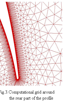
The computational domain developed around the tested blade was bounded by inlet plane located 70 mm upstream the leading edge and outlet plane located 140 mm downstream the trailing edge of the blade. Additionally, the periodical planes have been situated 120 mm above and 120 mm below the blade what corresponds to 1/2 of blade pitch. The triangular based unstructured mesh has been developed and consisted of 6580 nodes. To capture the phenomena in boundary layer the density of the mesh has been increased in the direction towards the wall (Fig. 3). The wall adjacent grid cells with the aspect ratio 1:56 are located at a distance y+=0.4 (0.05 mm). There is about 22 grid cells within boundary layer all around the blade profile.
The numerical simulations were performed for the Reynolds number Re=600,000 and for the outlet Mach number Ma= 0.3. The Mach number as well as the inflow and outflow velocity was increased 3.4 times to speed up the calculations but nevertheless the flow still could be considered as incompressible. At the inlet the following parameters were adjusted: turbulence intensity Tu=3.8%, the length scale λ= 3mm, inlet stagnation pressure Ps=28800 Pa, inlet stagnation temperature 293.2 °K, what was identical with experimental conditions. The static pressure at the outlet was kept constant.
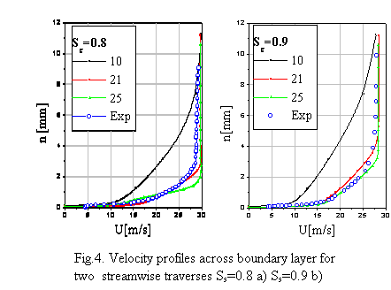
 The numerical analysis of the flow around the blade was preceded by the analysis of the grid quality in the boundary layer region. The grid independence tests have been performed on three meshes of the similar type, where the only difference was the number of mesh cells across boundary layer. The number of cells for consecutive meshes was 10, 20, 25 cells, which suits the adequately total number of nodes equal 4470, 6580, 8290. Fig.4 presents the comparison of calculated velocity profiles with superimposed experimental data for 69% and 71% distance of the suction side. As it could be seen the number of cells of the order 20 is sufficient to reproduce the velocity distribution within the boundary layer. It means also that the quality of the grid is good enough and that the transition location should not depend on its resolution. It was decided that the medium density grid will be kept in all further calculations.
© copyright ERCOFTAC 2004
Contributors: Andrzej Boguslawski - Technical University of Czestochowa

