UFR 3-01 References
Boundary layer interacting with wakes under adverse
pressure gradient - NLR 7301 high lift configuration
Underlying Flow Regime 3-01 © copyright ERCOFTAC 2004
References
[1] Carlson, J.R., Duquesne, N., Rumsey, C.L., Gatski, T.B. Computation of turbulent wake flows in variable pressure gradient. Computer & Fluids, Vol. 30, 2001, pp. 161-187.
[2] Rumsey, C.L., Ying, S.X. Prediction of high lift: review of present CFD capability. Progress in Aerospace Sciences, Vol. 38, 2002, pp. 145-180.
[3] Squire, L.C. Interactions between wakes and boundary-layers. Progress in Aerospace Sciences, Vol. 26, 1989, pp. 261-288.
[4] Zhou, M.D, and Squire, L.C. The interaction of a wake with a turbulent boundary layer. The Aeronautical Journal, Vol. 89, 1985, pp.72-81.
[5] Liu, X., Thomas, F.O., Nelson, R.C. An experimental investigation of wake development in arbitrary pressure gradient. AIAA Paper 99-0677, 1999.
[6] Kyriakides, N.K., Kastrinakis, E.G., Nychas, S.G., Goulas, A. Proceedings Inst. Mechanical Engineering, Vol. 210, 1996, p. 167.
[7] Piomelli, U., Choudhari, M.M., Ovchinnikov V., Balaras, E. Numerical simulations of wake/boundary layer interactions. AIAA 2003-0975, 2003.
[8] Berg, B. van der. Boundary Layer Measurements on a Two-Dimensional Wing with Flap, NLR TR 79009 U, 1979.
[9] Haase, W. et al. EUROVAL - An European Initiative on Validation of CFD codes. Notes on Numerical Fluid Mechanics, Vol. 42, 1992.
[10] Haase, W. et al. ECARP - European Computational Aerodynamics Research Projects: Validation of CFD Codes and Assessment of Turbulence Models. Notes on Numerical Fluid Mechanics, Vol. 58, 1997.
[11] Marini M. and Paoli R. Verification and Validation of Computational Fluid Dynamics Through the use of a Database. Proceedings ECCOMAS 2001.
[12] Gooden J.H.M and Lent M. Hot-Wire Measurements in the Two-Dimensional Wing Wake above a Trailing Edge Flap at a Condition Close to Maximum Lift, NLR CR 91038 C (Restricted), 1991.
[13] Larsson, T. Separated and high-lift flows over single and multi-element airfoils. ICAS 94-5.7.3, 1994.
[14] Godin, P, Zingg, D.W., Nelson, T.E. High-lift Aerodynamic computations with one and two equation turbulence models. AIAA Journal Vol. 35, No 2, 1997.
[15] Baldwin, B.S., Lomax, H. Thin layer approximation and algebraic model for separated turbulent flows. AIAA-paper 78-257, 1978.
[16] Spalart, P.R., Allmaras, S.A. A one-equation turbulence model for aerodynamic flows. AIAA Paper 92-0439, 1992.
[17] Jones, W.P., Launder, B.E. The prediction of laminarization with a two-equation turbulence model.. Journal of Heat and Mass Transfer, Vol. 15, 1972, pp. 301-314.
[18] Launder, B.E., Sharma, B.I. Application of the energy-dissipation model of turbulence to the calculation of flow near a spinning disc. Letters in Heat and Mass Transfer, Vol. 1, 1974, p. 131.
[19] Chien, K. Prediction of channel and boundary layer flows with a low Reynolds number turbulence model. AIAA Journal, Vol. 20, 1982, pp. 33-38.
[20] Lam, C.K.G., Bremhorst, K. A modified form of the k-ε model for predicting wall turbulence. Journal of Fluids Engineering, Vol. 103, 1981, pp. 456-460.
[21] Menter, F.R. Two-equation eddy-viscosity turbulence models for engineering applications. AIAA Journal, Vol. 32, 1994, pp. 1598-1605.
[22] Granville, P.S. Baldwin-Lomax factors for turbulent boundary layers in pressure gradients. AIAA Journal Vol. 25, 1987, pp. 1624-1627.
[23] Cebeci, T. and Smith, A.M.O. Analysis of Turbulent Boundary Layers. Series in Applied Mathematics and Mechanics XV, Academic Press, 1974.
24] Kalitzin, G., Gould, A.R.B and Benton, J.J. Application of two-equation turbulence models in aircraft design, AIAA Paper 96-0327, 1996.
[25] Speziale, C.G., Abid, R. and Anderson, E.C. Critical evaluation of two-equation models for near wall turbulence. AIAA Journal, Vol. 30, 1992, pp. 324-331.
[26] Wolfshtein, M. The velocity and temperature distribution in one-dimensional flow with turbulence augmentation and pressure gradient. Int. Journal of Heat and Mass Transfer, Vol. 12, 1969, p. 139.
[27] Shih, T-H., Zhu, J. and Lumley, J.L. A realisable Reynolds stress algebraic model. NASA TM 105993, 1993.
[28] An. A Selection of Experimental Test Cases for the Validation of CFD Codes. AGARD AR 303, 1994.
Appendix A: Figures from ECARP [10]
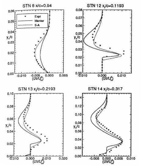
Remark: the figures are scanned from the ECARP Book [10], and use the figure numbering and captions of the original text.
|
|
|
|
|
|
|
|
|
|
|
|
|
|
|
|
|
|
|
|
|
|
|
|
|
|
|
|
|
|
|
|
|
|
|
|
|
|
|
|
|
|
|
|
|
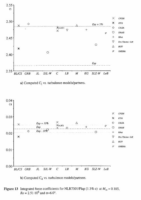
Table 4: Index to Turbulence Models used in ECARP figures reproduced on the following pages.
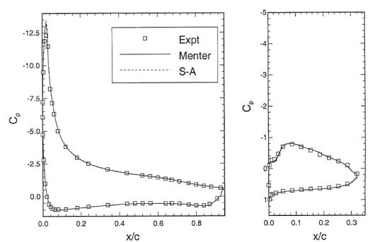
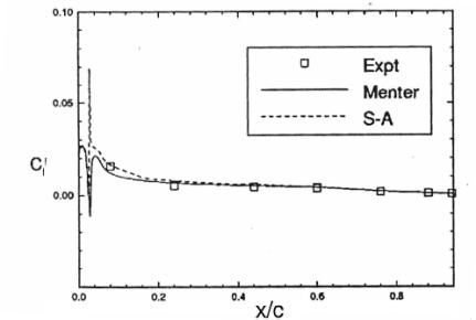
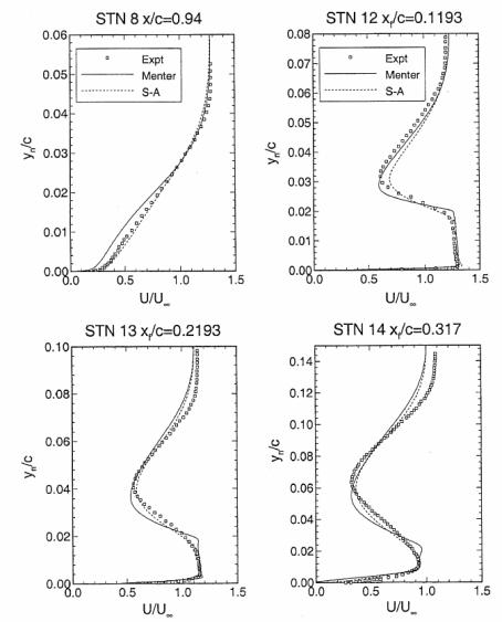
Appendix B: Figures from Godin [14]
© copyright ERCOFTAC 2004
Contributors: Jan Vos - CFS Engineering SA


